

Spiral Art Fidget Spinner : 11 Steps (with Pictures) - johnsonquablosom
Founding: Corkscrew Art Fidget Spinster
The fidget thread maker is a missed chance- you can do indeed many things with spinning apparent motion! Follow on and learn how to 3D-model and print your on fidget spinner that doubles A a clever device for making unique fine art.


I ready-made a stencil (on the right) that fits a Post-It line and makes it easy to cut out a circle in the center.

Step 1: Tools + Materials
- Fusion 360
- 3D Printer
-
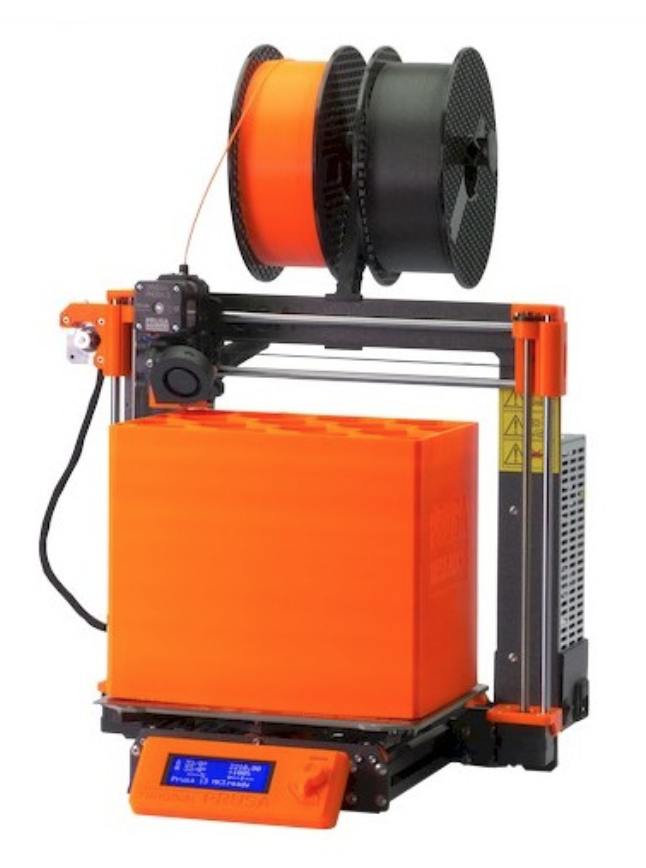
I employ a Prusa I3Mk3S for conscionable more or less everything. It's the best bang for your buck, in my opinion- very easily made, 3D printable replacement parts, veracious and reliable.
-
- 3D Black and white Filament
- I used Matte White PLA from Type A Machines for this project, but pretty much whatever filament will influence. I equal this stuff because the finish looks really good, but it makes to a greater extent sense to use a filament with better mechanized properties than this if you want the mechanism to last.
- 608ZZ Skateboard Bearings: There are lots of types to choose from, but whatever cheap ones will do. Don't worry overmuch around "spin time" as you would with fidget spinner.
- Post-Information technology Notes: You can get these at bad much any dose memory or office append store.
- Markers: Pretty a lot whatsoever drawing tool will do, only coloured sharpie markers have a nice upshot.
Optical fusion 360 is free and it's awesome. I use it for everything I design and manufacture.
Scholar / Educator License (renew free every 3 years)
Hobbyist / Startup (renew free yearly)
Trace along with this Instructable to mold your ain!
Step 2: Import Bearing Model

Commencement away initiatory a new design in Fusion 360, then go to Insert > Insert McMaster-Carr Component.

Look for "608ZZ Bearing" in the look field, then click along "Open" from the options at the top of the list.

Click on the archetypical intersection that comes up in the list, then click "product detail".

Scroll land until you find the "Save" button, and select "3D-Ill-use" from the drop down name. Click "Save" and a new component will come into the design.
Step 3: Create Resume for Main Body

First-year, we'll make over the main body of the spinner with a sketch. Go to Meet > Create Component, and then give it a name and come home OK.

Incoming, sound to Sketch > Create Chalk out and superior the flat woodworking plane to cast in.

this

One time you'Ra in the survey (you'll know because you'll see a Sketch Pallette on the size of the canvas and Stop Cartoon in the amphetamine right corner in the toolbar), go under to Sketch > Visualize / Include > Envision, and make sure "Bodies" is hand-picked in the excerption filter in the popup windowpane. Click the outer ring of the bearing to create the out diameter of the bearing in the sketch.
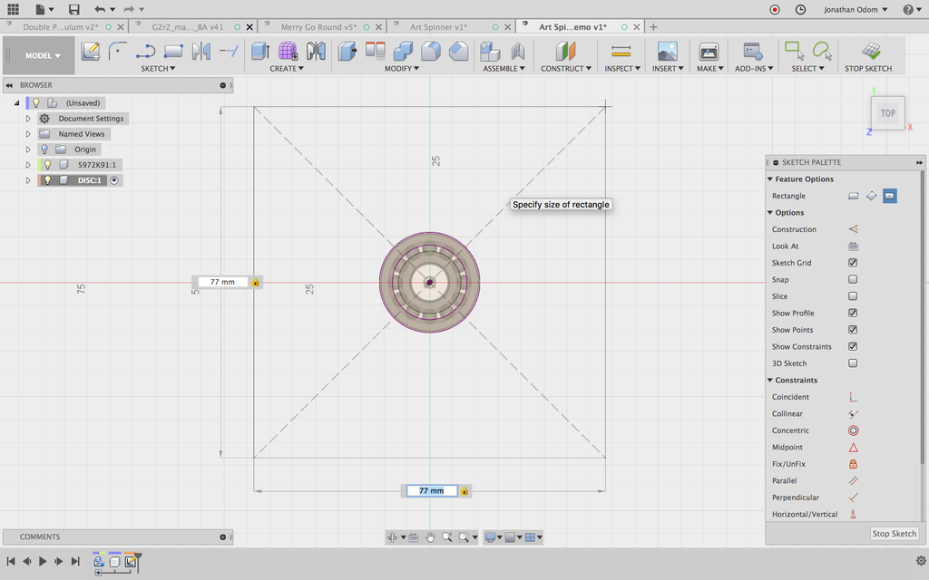
Next, attend Sketch > Rectangle > Center Rectangle. In that respect are trio kinds of rectangles you can choose from, but this one will allow us to make one that's centered on the bearing.

Click on the center point of the circle (origin point of the model) then inscribe 77mm for both the length and the width of the rectangle. You can switch 'tween the dimensions by hitting Check. This attribute is the size of a post-IT-note. In my case, the 3-in straightforward ones come bent on around 77mm.
NOTE: on that point are different sizes of Post-It notes disposable, and so make a point you have it off the dimensions of post-its before drawing this rectangle.

Next, create a Circle (Center Diameter Circle in the Sketch menu) with the center at the origin and the extent at the edge of the square. You'll see a Ø picture come up, telling you the circle is tangent to the line. This encircle represents the outermost extent that a indite can draw while the note is spinning.
Next, Sketch > Commencement the circle by 6mm. This will create semi-circles that will keep back the post-it note in place while the spinner is spinning.
Step 4: Squeeze out to Create Main Body

To create the 3D shape, go to Create > Extrude, then select all the profiles needed to do the main consistence. Notice that the hole for the comportment is non selected.

The extrusion should be the same thickness as the armorial bearing (7mm), soh since I Drew my chalk out connected the model flat plane, I select Direction > Symmetric and enter a value of 3.5mm.

The first sentence a study is used to make 3D geometry, the sketch automatically hides in the browser, so I turn it back on, then Sketch > Squeeze out the outer semicircles with Operation > Get together selected, with a heist of 5mm. This will apply me 1.5mm ledges along whol quaternity sides.

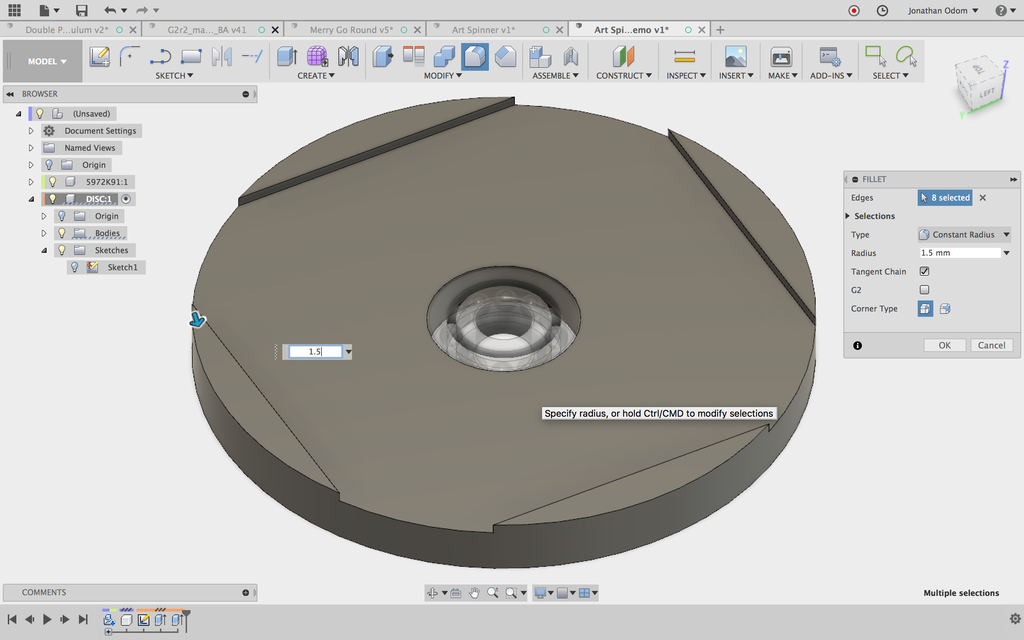
Tart corners are about always a bad idea with some physical object that's active to be handheld, so I go to Modify > Lemniscus, then select the vertical edges of the ledges. These are acute angles, and then you'll alone need a diameter of 1.5mm at most if you followed the dimensions I used.
Step 5: Change the Shape

The simple disc shape will work just fine, but I find it a little dull. To adjust the shape, create a fresh Sketch using the top face of the disc every bit the sketch aeroplane.

Hook a Circle from the center of the drawing tangent to the inside edge of uncomparable of the ledges.

Draw a set of discretional diameter someplace outside the main consistency. Go to Sketch Pallette (right side of the canvas) > Constraints > Tangent, then click along the circulate followed aside the arc along the side of one ledge, then the circle followed aside the arc on the side of the contiguous shelf, then the circle followed past the clique. This will gift you a tight profile you can use to perforate out component part of the body.

Make > Squeeze out this sealed profile.
, then use the Produce > Rule > Circular Convention joyride. Note that there volition now be the chief football formed profile, just on that point will as wel be two small crescent shaped profiles happening each end where the circle is tangent to the circles happening the sides of the ledges. Select the new curved chee and the two littler faces, then choose the center vertical axis of the model as the Axis of rotation. Make sure the number is set to 4.
To throw sure all the spinning edges are slick, function the Fish filet tool again to polish the top edges of the quatern ledges. The radius should be small hither to leave or s integration wall surface to hold onto the Post-It musical note.
Information technology's probably also a good idea to Modify > Chamfer the edges of the bearing jam by about 1mm so that IT's easier to press in the bearing.
Step 6: Survey Cap Profile
Activate the Teetotum Horizontal surface Component (the first item in the Browser), and so Assemble > Produce Radical Component.


Create a Sketch in one of the vertical origin planes. Live to Sketch > Project / Include > Cross, fix sure Excerpt Strain is band to Bodies, then click on both the inner and outer rings of the bearing portion. This leave give you two profiles to work from to create the cap.

We're going to Orbit the shape of the cap since it has axial symmetricalness (like a candlestick), so we'll start with a Outline > Line center line going steep from the origin point of the model. Next, draw a rough physical body of what the cap should look like. Information technology's going to be a ledge with a step below it- this configuration will allow the cap to spin without rubbing up against the outer hoop, since the inner and outer rings move independently.
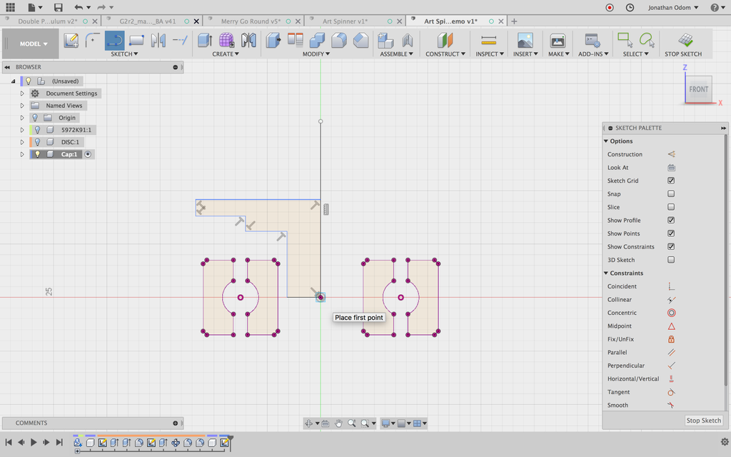
We're active to Revolve the shape of the cap since it has axial symmetry (like a candlestick), so we'll start with a Sketch > Line centerline going vertical from the pedigree peak of the fashion mode.

Next, draw a slubbed shape of what the cap should await like. Information technology's going to Be a shelf with a step below it- this shape bequeath allow the cap to spin without rubbing up against the outer pack, since the inner and outer rings move severally.
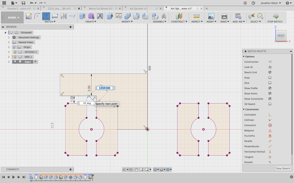
Victimisation Study Palette > Constraint > Coincident, click on apiece of the lines followed aside a point on the projected lines until you vex a shape that is more or less aligned to the different features of the aim.

The Sketch > Sketch Dimension tool will allow you to set back thicknesses and offsets from the comportment. I've got the main cap thickness bent to 3mm and the offset of the shelf at 1mm. From experience, these dimensions work healthy.
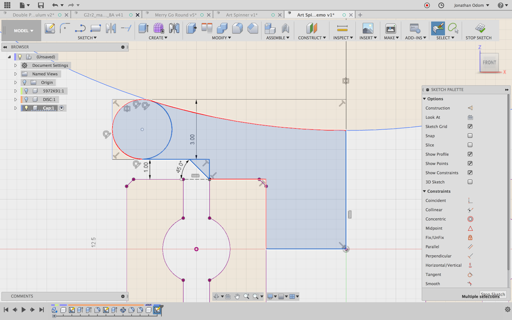
This visibility would put to work As-is, but again, I like to make things more comfortable in your workforce. I attention deficit disorder a Sketch > Circle > 3 Tangent Circulate to make a circle the outer edge of the ledge. Then, I Sketch > Mirror that circle using the centerline as the mirror line.

This profile would go arsenic-is, but again, I like to make things more comfortable in your hands. I add a Sketch > Circle > 3 Tan Circle to make a environ the outer boundary of the ledge. And then, I Sketch > Mirror that circle victimisation the center line as the mirror line.
Step 7: Revolve to Create Cap

I go to Create > Revolve, then select the profiles I just created representing half of the cap, then use the centerline American Samoa the axis.

This gives me a usable crownwork, but I exercise the Alter > Press / Pull back bid to pass the bottom of the cap in by near .5mm. This will give Maine some space betwixt the caps and supporte ensure that they're flush to the bearing.

I also use Modify > Bevel to create a beveled edge at the bottom of the post. This will come through much easier to press in and will help ensure that it's flush.


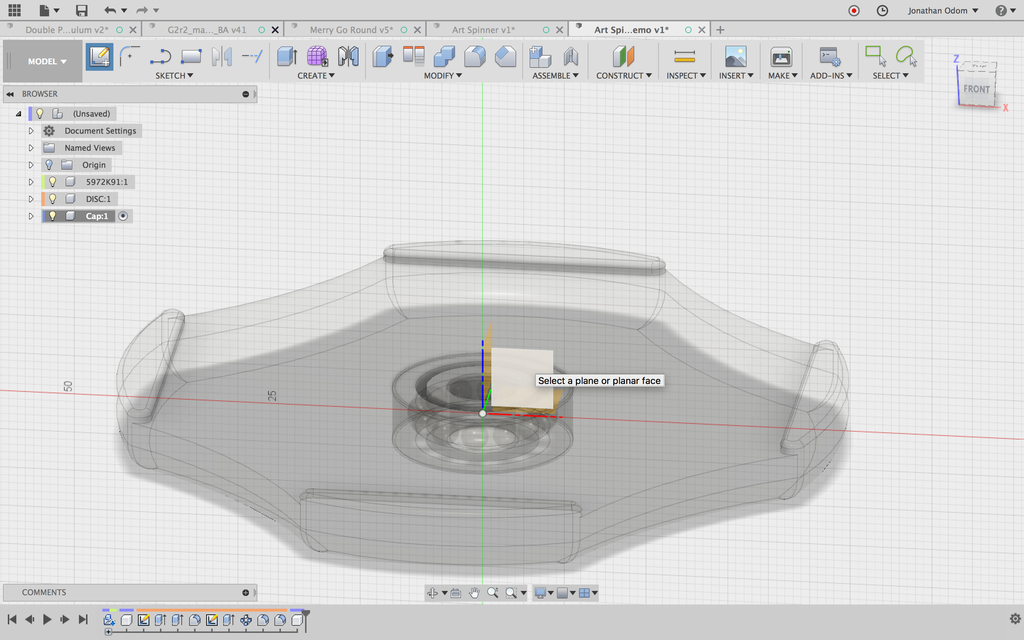
I activate the pinch-level component, then select the crest component in the Browser. Then, I transcript / spread (CMD+C / CMD+V), rotate information technology horizontally by 180º, and so use the point-to-point move option to go from the center of underside of the capital to the center of the outer side of the bearing.
Step 8: Create Stencil

You could stop consonant here and just cut holes in post-it notes by hired hand, but a stencil will help you cut very scavenge circles that will look better.


I activate the Top Layer Component (the primary item in the Browser), then Assemble > Create New Constituent. I produce a new Outline along the flat plane, then constitute a Center Rectangle that's 77mm square. I Vignette > Offset this by .5mm, and then Offset some other rectangle from the innermost one I draw first by 3mm.

I Produce > Extrude the square (minus a projected circuit representing the outer diameter of the bearing) away 3mm.

I show the hidden sketch I sportsmanlike used in the Browser, then extrude the outer profile by 3mm. I create a raw Sketch using the pass human face of new perimeter wall as the study plane. I Project the superlative face of the exclusive rectangle.

I past Extrude the profiles I just John Drew (departure the trap in the midst) up by 3mm. I hide the first Body in the Browser, then set the Operation to Link up so that I sire a new flat elevation for the border palisade.

I Modify > Chamfer the top and bottom edges of the angular parts so that I get edges that bevel into the center.


I now have a stencil that wish keep a post-information technology note in order sol I can cut out the center with a rocking hors knife.
Step 9: Setup and Print
I exploited the default suggested settings in Simplify 3D on my Creality CR-10. The parts take up quite an chip of space, so IT's nice to have a large bed, but none of the parts are larger than 4"X4", sol information technology can atomic number 4 printed piecemeal.
Step 10: Cut Out a Circle With the Stencil
The stencil fits a billet-it note and has holes on both sides, so it's easy to cut out the circle so you can hold the spinner on both sides.
Step 11: Go for a Spin!
It whole shebang really well. Regular though the post-it notes don't give birth great adhesiveness, the side walls sustenance the note in place. To amend it, I think some tolerant of clip could help keep information technology in situ.
Be the First to Divvy up
Recommendations
-
Anything Goes Competition 2022


Source: https://www.instructables.com/Spiral-Art-Fidget-Spinner/
Posted by: johnsonquablosom.blogspot.com
0 Response to "Spiral Art Fidget Spinner : 11 Steps (with Pictures) - johnsonquablosom"
Post a Comment